Wind Energy
Contents
[hide]Introduction
- Humans have been using wind power for at least 5000 BC to propel sailboats and sailing ships, and architects have used wind-driven natural ventilation in buildings since similarly ancient times. The use of wind to provide mechanical power came later.
- Harnessing renewable alternative energy is the ideal way to tackle the energy crisis, with due consideration given to environmental pollution, that looms large over the world.
- Renewable energy is also called "clean energy" or "green power" because it doesn’t pollute the air or the water. Wind energy is one such renewable energy source that harnesses natural wind power.
- This report presents a brief summary about wind energy and present day technologies available for horizontal wind turbines.
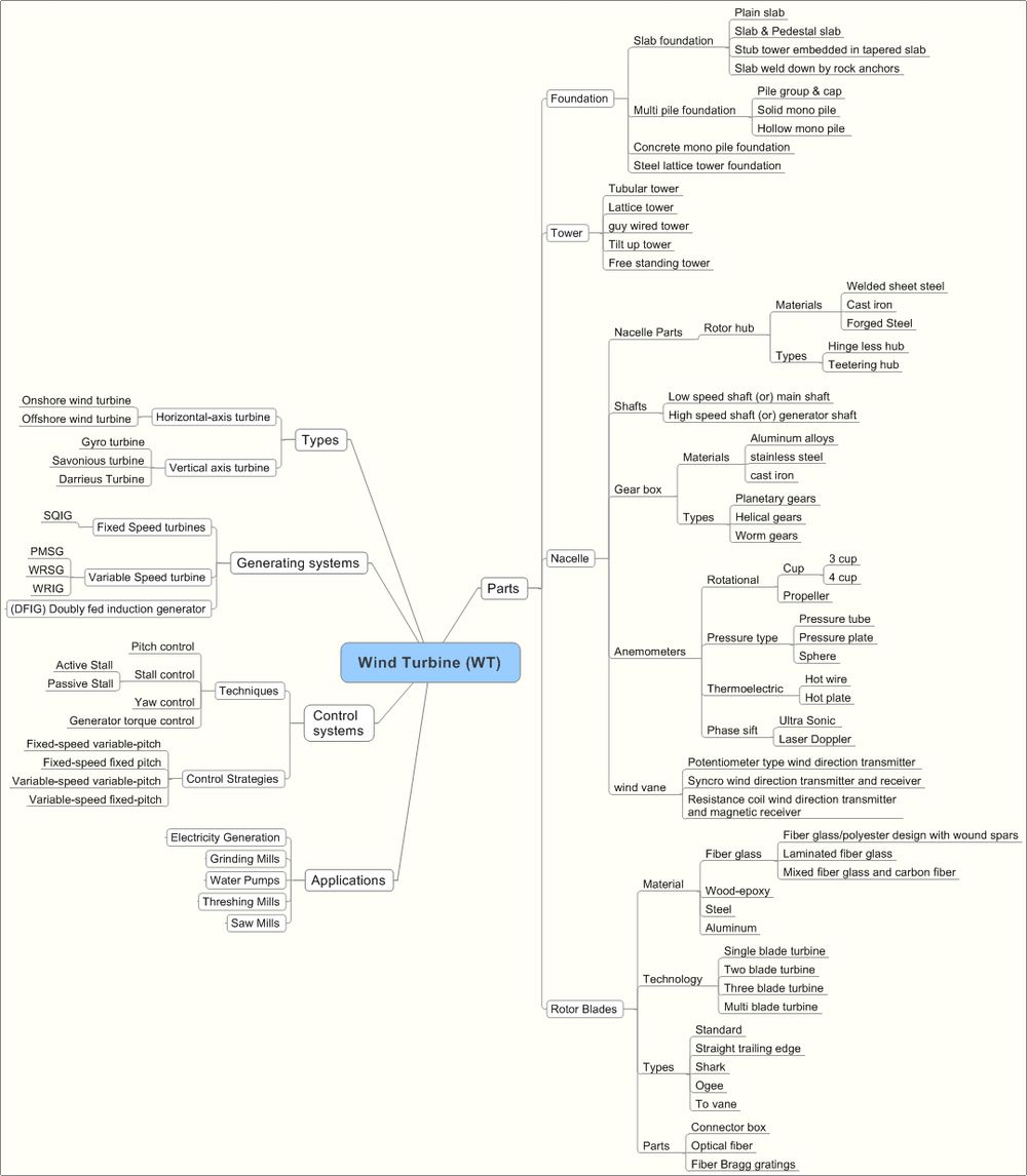
- A detailed taxonomy for horizontal axis wind turbines is presented covering parts of the turbine, control systems, applications among others
- A detailed landscape analysis of patent and non-patent literature is done with focus on Doubly fed induction generators used in the horizontal axis wind turbines for efficient power generation
- Existing products' information of major players in the market is compiled for Doubly-fed induction generators
- Existing market and future market prediction for wind energy based power generation is presented
Brief History of Wind Energy
Although the use of wind power started around 5000 BC, but electric power generation through wind energy started in 18th century and increasing drastically in 19th and 20th centuries. A brief view on developments on wind power sector are listed below.
- 1887 : Prof. James Blyth of Scotland used windmills for generating electricity.
- 1888 : Charles Brush developed the first wind-powered turbine that generated electricity in the United States based on emulated James Blyth work.
- 1927 : Joe Jacobs and Marcellus Jacobs improved the wind turbine generator for use in farms.
- 1931 : development of Darrieus wind turbine. It is a vertical axis turbine that rotates with wind from any direction.
- 1941: Largest mega watt range wind turbine was connected to the local electrical distribution system on the mountain known as Grandpa's Knob in Castleton, Vermont, USA.
- 1971: Denmark installed the first offshore wind farms
- 1990s: More than 2200 MW capacity of wind turbines are installed in california.
- 2003: the largest offshore wind farm North Hoyle was built in the United Kingdom.
- 2003-2010: Research is going is on wind turbines in blades structures, generators, operation and protection, efficiency of wind turbines.
Source: Wind Energy
The total installed wind power capacity from 2001 to 2010 is shown in fig. 1. All wind turbines installed by the end of year 2009 worldwide are generating 340 TWh per annum.
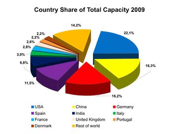
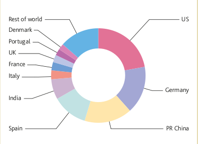
The country wise share of wind energy by the end of year 2009 is shown in fig. 2.
Source:World Wind Energy Report 2009
Working Principle of Wind Turbine
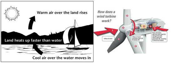
Wind is air in motion. It is a form of solar energy. Solar radiation heats every part of the Earth’s surface unevenly due to irregularities and rotation of earth. The flow of wind patterns are modified by the earth's terrain, bodies of water, and vegetative cover. When air moves, causing wind, it has kinetic energy. The kinetic energy of wind can be captured by a wind turbine and converted to other forms of energy such as electricity or mechanical power.
Sources:Wind Energy Basics,How Wind Turbines Work
Horizontal Axis and Vertical Axis Wind Turbines
Wind turbines are mainly classified into two types based on the axis in which turbine rotates. They are Horizontal axis wind turbine and vertical axis wind turbine.
| Horizontal axis wind turbines | Vertical axis wind turbines |
 Fig 4(a) Horizontal axis wind turbine |
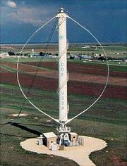 Fig 4(b)Vertical axis wind turbine |
Source:Different types of wind turbines
Horizontal Axis Wind Turbines
Onshore and Offshore Wind Turbines
| Onshore wind turbines | Offshore wind turbines |
Advantages
|
These are two types, namely Near shore and Off shore.
Advantages:
so, large turbines can be installed
|
Disadvantages
Sources:Wind Power,Types of Wind Farms |
Disadvantages:
Source:Offshore Technology |
 Fig 5(a) Onshore Wind turbines |
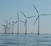 Fig5(b) Offshore wind turbines |
Parts of a Horizontal Axis Wind Turbine
The basic parts of a horizontal axis wind turbine(HAWT) is foundation, tower, nacelle, Generator, Rotor Blades.
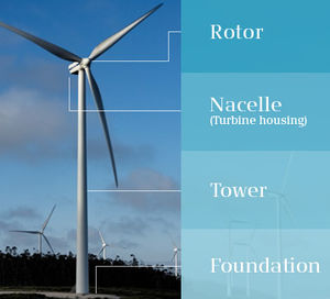
Foundation: A very good foundation is required to support the tower and various parts of a wind turbine which weighs in tonnes.
Tower
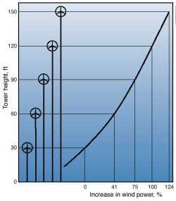
A tower that supports the nacelle and rotor hub at its top. These are made from tubular steel, concrete, or steel lattice. Height of the tower is an important in design of HWAT. Because wind speed increases with height, taller towers enable turbines to capture more energy and generate more electricity. Generally output power of the wind system increase with increase in height and also reduces the turbulance in wind. The theoritical view of tower height versus power out is shown in figure 7 . click on the link to get more about towers Wind Turbine Towers
Source:The Fundamentals of Wind Energy
| Different types of wind turbine towers | Structure |
| Tubular Tower: They are constructed from rolled steel plates welded together with flanges top and bottom, being sprayed with several coats of gray weatherproof paint at the construction yard. They have doors top and bottom allowing entrance to the vertical ladders inside used to access the power cables and the yaw mechanism. There are also a set of vertical ladders on the outside of the tower accessing the nacelle for maintenance and other checks. | 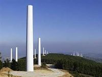 Fig 8(a) Tubular tower |
| Lattice tower: A Lattice tower can be constructed with perfectly shapped steel rods that are put together to form a lattice. These towers are very strong and inexpensive to manufacture and easy to transport and erect. | 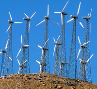 Fig 8(b) Lattice tower |
| Guyed wind tower: These are very strong and most economical when properly installed. But it requires more space around the tower for guy wires | 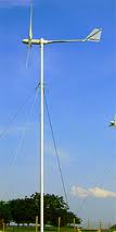 Fig 8(c) Guy tower |
| Tilt up wind towers:These type of towers are used for consumer wind energy. These turbines have locking system, while working the turbine is locked. It can easily ulocked and lowered to ground to perform repairs. | 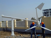 Fig 8(d) Tiltup tower |
| Free standing tower:These can be used for small wind turbines with cautions. | 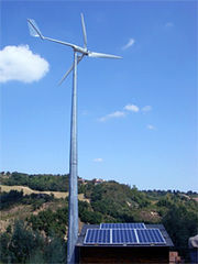 Fig 8(e) Free stand tower |
Sources:Winder Tower,Wind Towers
Blades
Wind turbine blades are used to extract the kinetic energy of wind and convert to mechanical energy. These blades are made up of fiber glass-reinforced polyester or wood-epoxy. Wind turbines have one or two or three or multiple blades based up on the construction. Most of the HAWT have three blades. These are connected to rotor hub. Multiple blade concept is used in earlier days for pumping water and grinding etc.
| Single blade HAWT | Two blade HAWT | Three blade HAWT |
It reduces the cost and weight of the turbine. These are rarely used due to tower shadow effects, needs counter weights on the other side of the blade, less stability.
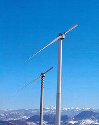 Fig 9(a) Single blade turbine |
It requires more complex design due to sustain of wind shocks. It is also less stable. It saves the cost and weight of one rotor blade.
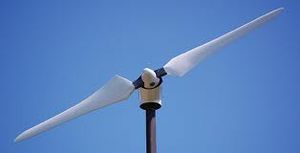 Fig 9(b) Two blade turbine |
Modern wind trubines uses three blade concept. Because this structure have hight strength to withstand heavy wind stroms. Less effect due to towe shadow. Produces high output
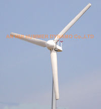 Fig 9(c) Three blade turbine |
Sources:Wind Turbine Blades,Wind Turbine Design Styles
Nacelle
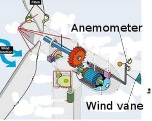
A housing which contains all the components which is essential to operate the turbine efficiently is called a nacelle. It is fitted at the top of a tower and includes the gear box, low- and high-speed shafts, generator, controller, and brakes. A wind speed anemometer and a wind vane are mounted on the nacelle.
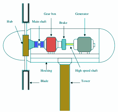
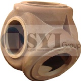
Hub A rotor hub is provided for coupling a wind turbine rotor blade and a shaft. The hub assembly consists of hub, bolts, blade bearings, pitch system and internals . Rotor hubs are made with welded sheet steel, cast iron, fored steel. The types of rotor hubs are
- Hingeless hub
- Teetering hub
Drive shaft
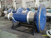
Drive shafts are a hollow or solid steel hardened shaft under very high stresses and considerable torque. Drive shafts are used to transfer rotational mechanical energy from blade hub to the generator to produce electricity. A wind turbine normally consists two shafts .
Main shaft: It is connected between blade hub and input to the gear box. It rotates at low speeds. So It is also called as 'low speed shaft'.
Generator shaft: It connects the gear box output to the generator input. It rotates at very high speed equals to the rating of the generator. It is also called 'high speed shaft'.
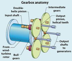
Gear box Gear box used in wind energy systems to change low speed high toque power coming from a rotor blade to high speed low torque power which is used for generator. It is connected in between main shaft and generator shaft to increase rotational speeds from about 30 to 60 rotations per minute (rpm) to about 1000 to 1800 rpm. Gearboxes used for wind turbine are made from superior quality aluminum alloys, stainless steel, cast iron etc.
The various gear boxes used in wind turbines are
- Planetary Gearbox
- Helical Gearbox
- Worm Gearbox
Generator
The output rotational mechanical energy of the gear box is connected to the generator through generator shaft. It works on the principle of 'Faraday's law of electromagnetic induction". It converts mechanical energy into electrical energy.
Sources:Wind Power Turbines, Rotor Hub Assembly,Gearbox for Wind Turbines, A Wind Turbine,The Wind Turbine Yaw Mechanism
Anemometers
Wind speed is the most important factor for determing the power content in the wind. The power content in the wind is directly proportional to cube of the wind velocity. Measuring wind speed is important for site selection. The device which is used for measuring wind speed is called anemometer. These are usally located on top of the nacelle.
Source:Anemometer
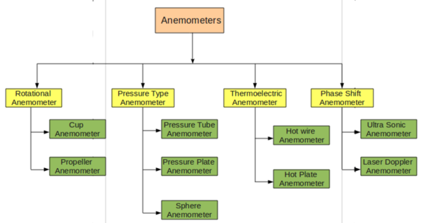
Types of anemometers The various types of anemometers are used in measuring wind speed is shown in flow chart below.
Source: Wind Power Energy
Wind vane Wind vanes are used to measure the wind directions and communicates with the yaw system to orient the turbine properly with respective to wind directions, to extract maximum amount of power from wind. Wind turbines are oriented to upstream wind or down stream wind.
Source:A Wind Turbine
Yaw Mechanism
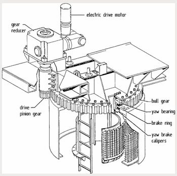
yaw mechanism turns the rotor into the upwind direction as the wind direction changes. Electric motors and gear boxes are used to keep the turbine yawed against wind. This can be also used as controlling mechanism during high wind speeds.
Source:The Wind Turbine Yaw Mechanism
Electrical Generating Systems
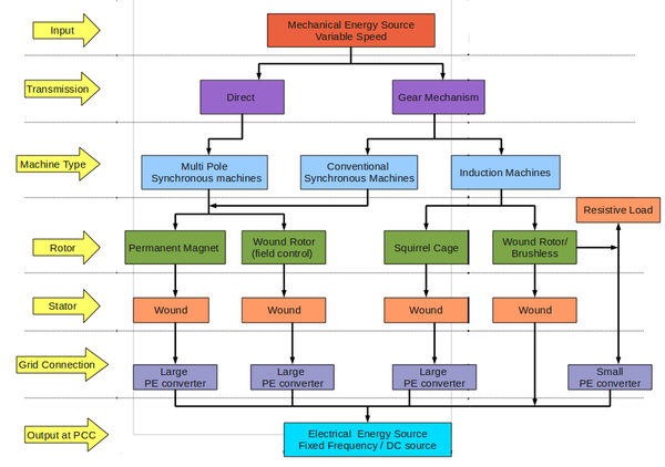
The various types of electrical generators are used in wind energy systems are shown in figure.
Source:Wind Turbine Generators
The most commonly used generator systems applied in wind turbines are are explained below.
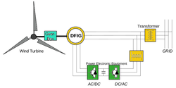
| Fixed speed generating systems | Variable speed generating systems | Doubly fed induction generator | |
| Structure | |||
| Machines | SQIG | PMSG/WRSG/WRIG | DFIG |
| Advantages | * Simple and low cost
* Low maintanace |
* Complete control of real and reactive powers
* High energy efficiency |
* Reduced capacity converter
* Decoupled control of active and reactive power flow * Smooth grid connection |
| Drawbacks | * No control on real and reactive power
* Less optimum power extraction capability * Poor power factor * High mechanical stress on turbine mechanical components |
* Additional cost of power electronics
* Limited fault ride through capability |
* Regular maintenance of slip ring and gearbox
* Limited fault ride-through capability |
Source:Inside wind turbines
Wind Turbine Control Systems
As the wind turbines increases in size and power, control systems plays a major role to operate wind turbines in safe region and also to improve efficiency and quality of power conversion. The main objectives of wind turbine control systems is
- Energy capture : Operating the wind turbine to extract maximum amount of energy considering safe restrictions like rated power, rated speed, cut-out wind speed etc.,
- Mechanical loads: protecting the systems from transient loads.
- Power quality: Conditioning the generated power with grid interconnection standards.
The various control techniques used in wind turbines are shown in table below
| Control System | Pitch contol | Yaw control | Stall control | Generator torque control |
| Description | A method of controlling the speed of a wind turbine by varying the orientation, or pitch, of the blades, and thereby altering its aerodynamics and efficiency.
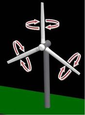 Fig 16(a) Pitch control Source:Blade Pitch Control |
The rotation of horizontal axis wind turbine around its tower to orient the turbine in upwind or down wind direction.
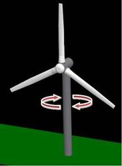 Fig 16(b) Yaw control Source:Wind Turbine Control Methods |
Stall control works by increasing the angle at which the relative wind strikes the blades (angle of attack). As the wind speed increases drag force on the blade increase and lift force gets reduces, thus finally reduces the speed of turbine.A fully stalled turbine blade, when stopped, has the flat side of the blade facing directly into the wind. Compare with furling.
Source:Stall-control basics |
As the aerodynamic torque control changes, rotor speed changes. it changes the output power frequency. A frequency converter is connected in between generator and the network to maintain generator power constant.
SourceWind Energy Control |
Taxonomy for Wind Turbines
Major IPC classes
A majority of patents describing wind turbines or wind energy are classified in the following IPC classifications.
| S.NO | IPC Classification | Description |
| 1 | F03D | WIND MOTORS |
| 2 | F16C | SHAFTS; FLEXIBLE SHAFTS; ELEMENTS OF CRANKSHAFT MECHANISMS; ROTARY BODIES OTHER THAN GEARING ELEMENTS; BEARINGS |
| 3 | F16H | GEARING |
| 4 | F03B | MACHINES OR ENGINES FOR LIQUIDS |
| 5 | H02K | DYNAMO-ELECTRIC MACHINES |
| 6 | H02P | CONTROL OR REGULATION OF ELECTRIC MOTORS, GENERATORS, OR DYNAMO-ELECTRIC CONVERTERS; CONTROLLING TRANSFORMERS, REACTORS OR CHOKE COILS |
| 7 | H02M | APPARATUS FOR CONVERSION BETWEEN AC AND AC, BETWEEN AC AND DC, OR BETWEEN DC AND DC, AND FOR USE WITH MAINS OR SIMILAR POWER SUPPLY SYSTEMS; CONVERSION OF DC OR AC INPUT POWER INTO SURGE OUTPUT POWER; CONTROL OR REGULATION |
| 8 | H02J | CIRCUIT ARRANGEMENTS OR SYSTEMS FOR SUPPLYING OR DISTRIBUTING ELECTRIC POWER; SYSTEMS FOR STORING ELECTRIC ENERGY |
| 9 | G06F | ELECTRIC DIGITAL DATA PROCESSING |
| 10 | G05F | SYSTEMS FOR REGULATING ELECTRIC OR MAGNETIC VARIABLES |
| 11 | H02H | EMERGENCY PROTECTIVE CIRCUIT ARRANGEMENTS |
Major Players
Major players in the Wind Energy sector include: General Electric, Vestas Wind Systems, Siemens AG, Mitsubishi Ltd, REPower Systems AG, Gamesa Innovation & Technology, Enercon, Nordex, Suzlon and Sinovel Wind Group Co. Ltd.
Like this report?
This is only a sample report with brief analysis
Dolcera can provide a comprehensive report customized to your needs
Doubly-fed Induction Generator
The present study on the IP activity in the area of horizontal axis wind turbines with focus on Doubly-fed Induction Generator (DFIG) is based on a search conducted on Thomson Innovation.
Control patents
| |
|
|
|
|
| |
|
|
|
Brushless doubly-fed induction machines employing dual cage rotors |
| |
|
|
|
Doubly fed induction machine |
| |
|
|
|
Control system for doubly fed induction generator |
| |
|
|
|
Power converter for doubly-fed power generator system |
| |
|
|
|
Variable speed wind turbine with doubly-fed induction generator compensated for varying rotor speed |
| |
|
|
|
Doubly-controlled asynchronous generator |
Thomson Innovation Search
A search is carried out using a combination of keywords and classifications in Thomson Innovation. The Classifications identified relevant to the scope of the search are:
IPC/ ECLA Classes
| IPC/ ECLA Class | Definition |
| F03D9/00 | Adaptations of wind motors for special use; Combinations of wind motors with apparatus driven thereby (aspects predominantly concerning driven apparatus) |
| F03D9/00C | Adaptations of wind motors for special use; Combinations of wind motors with apparatus driven thereby (aspects predominantly concerning driven apparatus)/ the apparatus being an electrical generator |
| H02J3/38 | Circuit arrangements for ac mains or ac distribution networks/ Arrangements for parallely feeding a single network by two or more generators, converters or transformers |
| H02K17/42 | DYNAMO-ELECTRIC MACHINES/ Asynchronous induction motors; Asynchronous induction generators/ Asynchronous induction generators |
| H02P9/00 | CONTROL OR REGULATION OF ELECTRIC MOTORS, GENERATORS, OR DYNAMO-ELECTRIC CONVERTERS; CONTROLLING TRANSFORMERS, REACTORS OR CHOKE COILS / Arrangements for controlling electric generators for the purpose of obtaining a desired output |
US Classes
| US Class | Definition |
| 290/044 | PRIME-MOVER DYNAMO PLANTS/ ELECTRIC CONTROL/ Fluid-current motors / Wind |
| 290/055 | PRIME-MOVER DYNAMO PLANTS/ FLUID-CURRENT MOTORS/ Wind |
| 318/727 | ELECTRICITY: MOTIVE POWER SYSTEMS/ INDUCTION MOTOR SYSTEMS |
| 322/047 | ELECTRICITY: SINGLE GENERATOR SYSTEMS/ GENERATOR CONTROL/ Induction generator |
Concept Table
| S.No | Concept1 | Concept1 | Concept1 |
| 1 | Doubly fed | Induction | Generator |
| 2 | Double output | Asynchronous | Machines |
| 3 | Dual fed | Systems | |
| 4 | Dual feed | ||
| 5 | Dual output |
Search Strategy
The databases covered in the search include: US Grant, GB App, US App, FR App, WO App, DE Util, EP Grant, DE Grant, EP App, DE App, JP Util, JP Grant, JP App, CN Util, CN App, KR Util , KR Grant, KR App, Other, DWPI
| S.No | No. of Hits | Remarks | Search String |
| 1 | 795 hits | Doubly fed induction generator keywords | CTB=(((((Doubl*3 or dual*3 or two) adj3 (power*2 or output*4 or control*4 or fed or feed*3)) near5 (induction or asynchronous)) near5 (generat*3 or machine*1 or dynamo*1)) OR DFIG); |
| 2 | 93 hits | Induction motor classes AND Doubly fed generator keywords | (UC=(318/727 OR 322/047) OR AIOE=(H02K001742)) AND ALL=(((((Doubl*3 or dual*3 or two) adj3 (power*2 or output*1 or control*4 or fed or feed*3)) near5 (generat*3 or machine*1 or dynamo*1))) OR DFIG); |
| 3 | 675 hits | Broad classes of generators AND Doubly fed induction generator keywords | (UC=(290/044 OR 290/055) OR AIOE=(F03D000900C OR H02J000338 OR F03D0009* OR H02P0009*)) AND ALL=(((((Doubl*2 or dual*3 or two) adj3 (power*2 or output*1 or control*3 or fed or feed*3)) near5 (induction or asynchronous)) near5 (generat*3 or machine*1 or dynamo*1)) or DFIG); |
| 4 | 240 hits | French keywords | CTB=((((Doubl*3 or dual*3or ADJ two or deux) near4 (nourris or feed*3 or puissance or sortie*1 or contrôle*1)) near4 (induction or asynchrone*1) near4 (générateur*1 or generator*1 or machine*1 or dynamo*1)) or DFIG); |
| 5 | 282 hits | German keywords | CTB=(((((doppel*1 or dual or two or zwei) adj3 (Ausgang or Ausgänge or Kontroll* or control*4 or gesteuert or Macht or feed*1 or gefüttert or gespeiste*1)) or (doppeltgefüttert or DOPPELTGESPEISTE*1)) near4 (((Induktion or asynchronen) near4 (generator*2 or Maschine*1 or dynamo*1)) or (INDUKTION?MASCHINEN or INDUKTION?generatoren or Asynchronmaschine or Asynchrongenerator))) or DFIG); |
| 6 | 920 hits | ALL=(((((((Doubl*3 or dual*3) adj3 (power*2 or output*4 or control*4 or fed or feed*3))) near5 (generat*3 or machine*1 or dynamo*1))) same wind) or (DFIG same wind)) AND DP>=(18360101); | |
| 7 | 1434 hits (702 INPADOC Families) | Combined Query | 1 OR 2 OR 3 OR 4 OR 5 OR 6 |
Taxonomy
Sample Analysis
A sample of 139 patents from the search are analysed based on the taxonomy.
Provided a link below for sample spread sheet analysis for doubly-fed induction generators.
Patent Analysis
| |
|
|
|
|
| |
| |
| |||||
| |
|
|
|
Method of and apparatus for operating a double-fed asynchronous machine in the event of transient mains voltage changes | The short-circuit-like currents in the case of transient mains voltage changes lead to a corresponding air gap torque which loads the drive train and transmission lines can damages or reduces the drive train and power system equipments. | The method presents that the stator connecting with the network and the rotor with a converter. The converter is formed to set a reference value of an electrical amplitude in the rotor, by which a reference value of the electrical amplitude is setted in the rotor after attaining a transient mains voltage change, such that the rotor flux approaches the stator flux. |
| |
|
|
|
Variable speed wind turbine with doubly-fed induction generator compensated for varying rotor speed | The DFIG system has poor damping of oscillations within the flux dynamics due to cross coupling between active and reactive currents, which makes the system potentially unstable under certain circumstances and complicates the work of the rotor current controller. These oscillations ca damage the drive train mechanisms. | A comprensation block is arranged, which feeds a compensation control output to the rotor of the generator. The computation unit computes the control output during operation of the turbine to compensate partly for dependencies on a rotor angular speed of locations of poles of a generator transfer function, so that the transfer function is made independent of variations in the speed during operation of the turbine which eliminates the osicllations and increases the efficinecy of the wind turbine. |
| |
|
|
|
Current limitation for a double-fed asynchronous machine | Abnormal currents can damage the widings in the doubly- fed induction gnerator. Cntrolling these currents with the subordinate current controllers cannot be an efficient way to extract the maximum amount of active power. | The method involves delivering or receiving of a maximum permissible reference value of an active power during an operation of a double-fed asynchronous machine, where predetermined active power and reactive power reference values are limited to a calculated maximum permissible active and reactive power reference values, and hence ensures reliable regulated effect and reactive power without affecting the power adjustment, the rotor is electrically connected to a pulse-controlled inverter by slip rings with a static frequency changer, and thus a tension with variable amplitude and frequency is imposed in the rotor. |
| |
|
|
|
Method and system of control of the converter of an electricity generation facility connected to an electricity network in the presence of voltage sags in said network | Double-fed asynchronous generators are very sensitive to the faults that may arise in the electricity network, such as voltage sags. During the sag conditions the current which appears in said converter may reach very high values, and may even destroy it. | During the event of a voltage sag occurring, the converter imposes a new setpoint current which is the result of adding to the previous setpoint current a new term, called demagnetizing current, It is is proportional to a value of free flow of a generator stator. A difference between a value of a magnetic flow in the stator of the generator and a value of a stator flow associated to a direct component of a stator voltage is estimated. A value of a preset calculated difference is multiplied by a factor for producing the demagnetizing current. |
| |
|
|
|
Variable speed wind turbine having an exciter machine and a power converter not connected to the grid | a) The active switching of the semiconductors of the grid side converter injects undesirable high frequency harmonics to the grid.b) The use of power electronic converters (4) connected to the grid (9) causes harmonic distortion of the network voltage. | Providing the way that power is only delivered to the grid through the stator of the doubly fed induction generator, avoiding undesired harmonic distortion. Grid Flux Orientation (GFO) is used to accurately control the power injected to the grid. An advantage of this control system is that it does not depend on machine parameters, which may vary significantly, and theoretical machine models, avoiding the use of additional adjusting loops and achieving a better power quality fed into the utility grid. |
| |
|
|
|
Frequency converter for a double-fed asynchronous generator with variable power output and method for its operation | Optislip circuit with a resistor is used when speed is above synchronous speed, results in heating the resistor and thus the generator leads to limitation of operation in supersynchronous range which results tower fluctions. | Providing a back-to-back converter whic contains the inverter circuit has direct current (DC) inputs , DC outputs, and a rotor-rectifier connected to a rotor of a dual feed asynchronous generator. A mains inverter is connected to a power grid, and an intermediate circuit connects one of the DC inputs with the DC outputs. The intermediate circuit has a semiconductor switch between the DC outputs, an intermediate circuit condenser between the DC inputs, and a diode provided between the semiconductor switch and the condenser. Thus the sysem is allowed for any speed of wind and reduces the tower fluctuations. |
| |
|
|
|
Power converter for doubly-fed power generator system | During the ground faults, excess currents is induced in the secondary windings and flows into power converter connected o secondar side and may danage the power converter. Conventional methos of incresing the capacity of the power cnverter increases system cost , degrade the system and takes time to activate the system to supply power again. | The generator provided with a excitation power converter connected to secondary windings of a doubly-fed generator via impedance e.g. reactor, and a diode rectifier connected in parallel to the second windings of the doubly-fed generator via another impedance. A direct current link of the rectifier is connected in parallel to a DC link of the converter. A controller outputs an on-command to a power semiconductor switching element of the converter if a value of current flowing in the power semiconductor switching element is a predetermined value or larger. |
| |
|
|
|
System and method of operating double fed induction generators | Wind turbines with double fed induction generators are sensitive to grid faults.Conventional methods are not effective to reduce the shaft stress during grid faults and slow response and using dynamic vltage restoreer (DVR) is cost expensive. | The protection system has controlled impedance devices.Impedance device has bidirectional semiconductors such triac, assembly of thyristors or anti-parallel thyristors. Each of the controlled impedance devices is coupled between a respective phase of a stator winding of a double fed induction generator and a respective phase of a grid side converter. The protection system also includes a controller configured for coupling and decoupling impedance in one or more of the controlled impedance devices in response to changes in utility grid voltage and a utility grid current. High impedance is offered to the grid during network faults to isolate the dual fed wind turbine generator. |
| |
|
|
|
Control and protection of a doubly-fed induction generator system | A short-circuit in the grid causes the generator to feed high stator-currents into the short-circuit and the rotor-currents increase very rapidly which cause damage to the power-electronic components of the converter connecting the rotor windings with the rotor-inverter. | The converter is provided with a clamping unit which is triggered from a non-operation state to an operation state, during detection of over-current in the rotor windings. The clamping unit comprises passive voltage-dependent resistor element for providing a clamping voltage over the rotor windings when the clamping unit is triggered. |
| |
|
|
|
Method for controlling doubly-fed machine | Controlling the double fed machines on the basis of inveter control to implement the targets set for the machine, this model is extremely complicated and includes numerous parameters that are often to be determined. | A method is provided to use a standard scalar-controlled frequency converter for machine control. A frequency reference for the inverter with a control circuit, and reactive power reference are set for the machine. An rotor current compensation reference is set based on reactive power reference and reactive power. A scalar-controlled inverter is controlled for producing voltage for the rotor of the machine, based on the set frequency reference and rotor current compensation reference. |
Click on the link below to view detailed analysis sheet for Doubly-Fed Induction Generator Patent Literature
* Sample analysis on Doubly-Fed Induction Generator-Patent Literature
Top Cited Patents
| |
|
|
|
| |
US5289041A | Speed control system for a variable speed wind turbine | |
| |
US4982147A | Power factor motor control system | |
| |
US5028804A | Brushless doubly-fed generator control system | |
| |
US5239251A | Brushless doubly-fed motor control system | |
| |
US6856038B2 | Variable speed wind turbine having a matrix converter | |
| |
WO1999029034A1 | A method and a system for speed control of a rotating electrical machine with flux composed of two quantities | |
| |
WO1999019963A1 | Rotating electric machine | |
| |
US7015595B2 | Variable speed wind turbine having a passive grid side rectifier with scalar power control and dependent pitch control | |
| |
US4763058A | Method and apparatus for determining the flux angle of rotating field machine or for position-oriented operation of the machine | |
| |
US7095131B2 | Variable speed wind turbine generator | |
Article Analysis
| |
|
|
|
|
| |
Study on the Control of DFIG andIts Responses to Grid Disturbances | |
Power Engineering Society General Meeting, 2006. IEEE | Presented dynamic model of the DFIG, including mechanical model, generator model, and PWM voltage source coverters. Vector control strategies adapted for both the RSC and GSC to control speed and reactive power independently. controlling desigining methods, such as pole-placement method and the internal model control are used. Matlab/Simulink is used for simulation. |
| |
Application of Matrix Converter for Variable Speed Wind Turbine Driving an Doubly Fed Induction Generator | |
Power Electronics, Electrical Drives, Automation and Motion, 2006. SPEEDAM 2006. | A matrix converter is replaced with back to back converter in a variable speed wind turbine using doubly fed induction generator. Stable operation is achieved by stator flux oriented control techinque and the sytem opertaed in both sub and super synchronous modes, achieved good results. |
| |
Optimal Power Control Strategy of Maximizing Wind Energy Tracking and Conversion for VSCF Doubly Fed Induction Generator System | |
Power Electronics and Motion Control Conference, 2006. IPEMC 2006. CES/IEEE 5th International | Proposed a new optimal control strategy of maximum wind power extraction stratagies and testified by simulation. The control algorithm also used to minimize the losses in the generator. The dual passage excitation control strategy is applied to decouple the active and reactive powers. With this control system, the simulation results shows the good robustness and high generator efficiency is achieved. |
| |
A Torque Tracking Control algorithm for Doubly–fed Induction Generator | |
Journal of ELECTRICAL ENGINEERING | Proposed a torque tracking control algorithm for Doubly fed induction generator using PI controllers. It is achieved by controlling the rotor currents and using a stator voltage vector reference frame. |
| |
Fault Ride Through Capability Improvement Of Wind Farms Using Doubly Fed Induciton Generator | |
Universities Power Engineering Conference, 2008. UPEC 2008. 43rd International | An active diode bridge crowbar switch presented to improve fault ride through capability of DIFG. Showed different parameters related to crowbar such a crowbar resistance, power loss, temparature and time delay for deactivation during fault. |
Click on the link below to view detailed analysis sheet for Doubly-Fed Induction Generator-Non Patent Literature
Top cited Articles
Click on the link to download worksheet
IP Trend Analysis
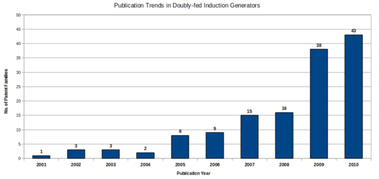
Patenting activity has seen high growth rate in the last two years.
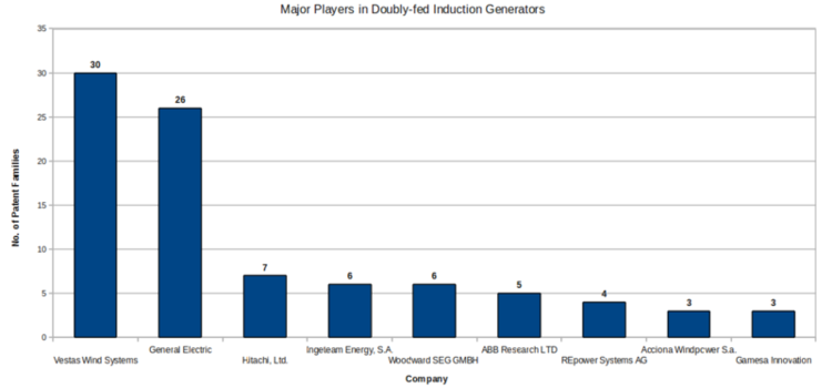
Vestas Wind Systems and General Electric are the major players in this technology field.
Dashboard
Dashboard Link
Dashboard for doubly fed induction generator
- Flash Player is essential to view the Dashboard
Products
| |
|
|
|
| |
|
|
Rated power 2.0 MW; Operating temperature -30°C to 40°; Frequency: 50 Hz/60 Hz;Number of poles 4-pole |
| |
Rated power 1.8/2.0 MW; Operating temperature -30°C to 40°; Frequency: 50 Hz/60 Hz;Number of poles 4-pole (50 Hz)/6-pole (60 Hz) | ||
| |
Rated power 3.0 MW; Operating temperature -30°C to 40°; Frequency: 50 Hz/60 Hz;Number of poles 4-pole | ||
| |
|
|
Rated voltage 690V; rated current 1670A; frequency 50Hz; rotor rated voltage 1840V; rotor rated current 670A;, Poles 4 Pole; rated speed 1660rpm; power speed range of 520-1950rmp; Insulation Class H; protection class IP54; center height H = 500mm; motor temperature rise =<95K |
| |
|
|
Rated Voltage 690 V ac; Frequency 50 Hz; Protection class IP 54; Number of poles 4; Rotational speed 900:1,900 rpm (rated 1,680 rpm) (50Hz); Rated Stator Current 1,500 A @ 690 V; Power factor (standard) 0.98 CAP - 0.96 IND at partial loads and 1 at nominal power. *; Power factor (optional) 0.95 CAP - 0.95 IND throughout the power range. |
| |
|
|
Rated power 2.5 MW; Rated volatge 690V; frequency 50/60Hz; Cooling systems: liquid/air. |
| |
Rated power 2.5 MW; Rated volatge 690V; frequency 50/60Hz; Cooling systems: liquid/air. | ||
| |
Rated power 2.4 MW; Rated volatge 690V; frequency 50/60Hz; Cooling systems: liquid/air. | ||
| |
Rated power 2.5 MW; Rated volatge 690V; frequency 50/60Hz; Cooling systems: liquid/air. | ||
| |
|
|
|
| |
|
|
Rated power1550KW; Rated speed1755 r/min; Speed range975~1970 r/min;Stator rated voltage690V±10%; Stator rated current1115A; Rotor rated voltage320V; Rotor rated current430A;Winding connectionY / Y; Power factor0.95 (Lead) ~ 0.95Lag; Protection classIP54; Insulation classH; Work modeS1; Installation modeIM B3; Cooling modeAir cooling; Center high500mm; Pole number4; Weight6950kg |
| |
|
|
Rated Power 0.5 -1 KW; Rated voltage : 460/ 575/ 690 V; frequency 50/ 60 Hz; No. Of Poles 4/6; Ambient Temp.(°C) -40 to 50; Speed Range (% of Synch. Speed) 68% to 134%; Power Factor (Leading) -0.90 to +0.90 ; Insulation Class H/F; Efficiency >= 96% |
| |
Rated Power 1-2 kW; Rated voltage : 460/ 575/ 690 V; frequency 50/ 60 Hz; No. Of Poles 4/6; Ambient Temp.(°C) -40 to 50; Speed Range (% of Synch. Speed) 68% to 134%; Power Factor (Leading) -0.90 to +0.90 ; Insulation Class H/F; Efficiency >= 96% | ||
| |
Rated Power 2-3kW; Rated voltage : 460/ 575/ 690 V; frequency 50/ 60 Hz; No. Of Poles 4/6; Ambient Temp.(°C) -40 to 50; Speed Range (% of Synch. Speed) 68% to 134%; Power Factor (Leading) -0.90 to +0.90 ; Insulation Class H/F; Efficiency >= 96% | ||
| |
|
Rated Power 1500MW; Voltage 690 V ac; Frequency 50 Hz; Protection class IP 54; Number of poles 4; Rotational speed 900:1,900 rpm (rated 1,680 rpm) (50Hz); Rated Stator Current 1,500 A @ 690 V; Power factor (standard) 0.98 CAP - 0.96 IND at partial loads and 1 at nominal power. *; Power factor (optional) 0.95 CAP - 0.95 IND throughout the power range. | |
| |
Rated Power 3000MW; Voltage 690 V ac; Frequency 50 Hz; Protection class IP 54; Number of poles 4; Rotational speed 900:1,900 rpm (rated 1,680 rpm) (50Hz); Rated Stator Current 1,500 A @ 690 V; Power factor (standard) 0.98 CAP - 0.96 IND at partial loads and 1 at nominal power. *; Power factor (optional) 0.95 CAP - 0.95 IND throughout the power range. | ||
| |
|
|
Rated power 1.5/2.5 MW; Frequency (Hz) 50/60; |
Market Research
Major Players
Vestas Wind Systems, General Electric and Gamesa Innovation & Technology are the top players in terms of installed power capacity in the year 2007.
| |
|
| |
| |
|
| |
| |
|
| |
| |
|
| |
| |
|
| |
| |
|
| |
| |
|
| |
| |
|
| |
| |
|
| |
| |
|
| |
| |
|
| |
Source:Wind power companies
Market Overview
- The world's wind industry defied the economic downturn in 2008 and by he end of the year 2009, the sector saw its annual market grow by 41.5% over 2008, and total global wind power capacity increased by 31.7% to 158GW in 2009
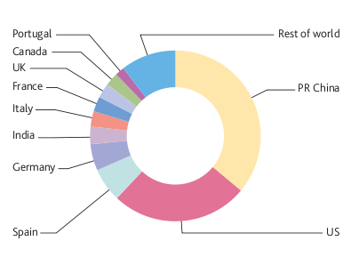
- US, China and Germany together hold more than 50% of the global wind power capacity
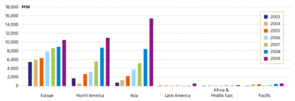
- Asia and North America have seen tremendous growth in the installed wind power capacity over the last 6 years
- Asia was the world's largest regional market for wind energy with capacity additions amounting to 15.4GW. China was the world's largest market in 2009, more than doubling its capacity from 12.1GW in 2008 to 25.8GW, adding a staggering 13.8GW of capacity
- China and the US account for more than 60% of the new installed capacity of 38.3GW in 2009. India's total installed capacity increased to 10.9GW with 1.3GW of new installed capacity in 2009
- The 2009 market for turbine installations was worth about 45 bn € or 63 bn US$ and about half a million people are now employed by the wind industry around the world
Market Forecast
- Global wind power capacity could reach 2,300 GW by 2030, providing up to 22% of the world's electricity needs, from the existing 2.2% in 2010.
- Global wind capacity will stand at 409GW up from 158GW at the end of 2008. During 2014, 62.5 GW of new capacity will be added to the global total, compared to 38.3 GW in 2009
- The annual growth rates during this period will average 20.9% in terms of total installed capacity, and 10.3% for annual market growth
- Three regions will continue to drive the expansion of wind energy capacity: Asia, North America and Europe
- Asia will remain the fastest growing market in the world, driven primarily by China, which is set to continue the rapid upscaling of its wind capacity and hold its position as the world’s largest annual market. Annual additions are expected to be well over 20 GW in China by 2014
- Sustained growth is also expected in India, which will increase its capacity steadily by 2 GW every year, and be
complemented by growth in other Asian markets, including Japan, Taiwan, South Korea and the Philippines, and potentially some others
- By 2014, the annual market will reach 14.5 GW, and a total of 60 GW will be installed in Europe over this five year period
Source:GWEC's Global Wind Report 2009
Like this report?
This is only a sample report with brief analysis
Dolcera can provide a comprehensive report customized to your needs
Contact Dolcera
| Samir Raiyani |
|---|
| Email: info@dolcera.com |
| Phone: +1-650-269-7952 |

